
PART01:
Reading and writing firmware.
SOURCE SERIES OF ARTICLES : Here !

In this series of articles, I want to share my experiments in the field of chip tuning at home for a ZMZ-51432 diesel engine equipped with a Bosch EDC16C39-H6.1 ECM unit.
Most Patriot owners want to improve engine performance. However, if the gasoline versions are practically not amenable to chip tuning, then the turbodiesel gives great opportunities here.
To begin with, I plan to turn off what prevents the engine from driving. Namely, the environmental restrictions are the exhaust gas recirculation system (EGR) and the anti-smoke function. I also plan to adapt the firmware for the new turbine TKR 50.04.07 from ZAO NPO Turbotekhnika (there is information that the plant began to install a new "improved" firmware in October 2013 - but I do not have it yet, I will be glad if you send it). As for the increase in power and torque, I think that it is quite possible to add 20-30 hp. and 50-60 Nm of torque, but at the current stage I think this is inappropriate. With a new turbine, even on the old factory firmware, the car runs very briskly, and it's never too late to break the transmission and kill the engine.
Many people think that chip tuning requires expensive equipment. This is not true.
SO :
Equipement using :
BDM100 Chinese CLONE
EDC16C39-H6.1
First of all :
- We remove the ECM from the car.
- next step is to open the block. Here you need to make a reservation - it is quite difficult to open the block without damaging the lid, especially if you open it for the first time. The fact is that the EDC16 blocks are sealed and very well sealed with a black, very viscous strong sealant, and the back cover of the block, without removing which you will not get access to the BDM interface, is made of duralumin, therefore, it bends and scratches easily. However, when the unit is installed in the car, the damage to the back cover is not visible, so there should be no questions from the warranty providers.
 |
| Cover condition after opening the block |
 |
| COVER REMOVE |
The next step is to connect the programmer. Here you will need a soldering iron with a very thin tip and perhaps a little help from your electronics friend. I used a soldering iron with a 0.5mm tip. We take the 10-wire cable that comes with the programmer, cut off one connector, divide the cable into separate conductors (about 10 cm long), clean and tin the ends. I took sticky notes from the old videotapes, signed them in accordance with the pinout of the connector on the programmer and glued them to the wiring so that they would not be confused when soldering (the first conductor is marked in red on the loop).
With a piece of electrical tape we attach the cable to the controller case (so as not to accidentally pull and pull out the wires), then carefully solder the conductors to the contact pads of the block in accordance with the pinout (you cannot press, otherwise damage the contact pads). That's it, the block is ready for flashing.
 |
| connectore |
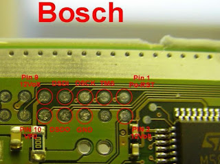 |
Pinout from the block side |
After rechecking all connections (first of all, ground and 12V), we connect the loop to the programmer (the programmer should already be connected to USB and a 12V power supply). We launch the software. We press the "ON" button. If everything is fine, the software will swear at an unknown controller model and offer to choose one of the existing ones. I chose “BOSCH EDC16 Iveco”.

Next, on the "Single File" tab, click "Read ECU". After selecting the file name, the process of reading the contents of the block will begin, at the end the power will turn off.

In the window "Save ECU data" the program will ask you to enter additional data. In this case, some of the fields, for example “ECU Hardware number” and “ECU Software number”, will already be filled in. Pay attention to these fields - they contain the hardware revision of the controller and the version of the factory software. In my case, this is:
ECU HW: 0281006291
ECU SW: 1037523313
The read file, about 450 kilobytes in size, contains the controller's flash memory (2048 kilobytes) in compressed format and the controller's additional non-volatile memory (4 kilobytes). Flash memory is the same firmware for all machines. We will modify it in the future in order to achieve changes in the operation of the engine. Additional non-volatile memory is used for storing machine-specific parameters - VIN-code, injector codes, current mileage and engine hours, etc. Therefore, it is very important to make a snapshot of the current state of the controller before any modification, so that if something happens, you can roll back.
To unpack the read data into separate files available for editing, press the “Export” button, then in the “Export File” section press the “29BL / 28F / M58W” button to save the flash memory file, and the “Serial E2prom” button to save additional non-volatile memory file.
To write a new or modified firmware, you need to collect the file in a compressed format, combining the new firmware and your current file of additional non-volatile memory in it. In general, the “Advanced” tab provides for recording a separate flash memory, but, apparently, due to the fact that the software does not know this controller, the buttons on the tab are inactive. Therefore, press the "Export" button, select the last read (compressed) file, in the "Import File" section, press "29BL / 28F / M58W" and select the new firmware file. Then press "Serial E2prom" and select the previously saved file. Click "Save As ..." and save the finished file.
The process of writing the firmware, in general, is similar to the process of reading, only you need to press "Write ECU".
I will tell you how to prepare modified firmware in the next article.
UPDATE: For some, the programmer does not work out of the box, because flashed for the wrong.software version .


No comments:
Post a Comment